This paper introduces an innovative approach to enhancing the quality of electronic component assembly through real-time, inline inspection utilizing AI-powered deep learning techniques. The primary objective is to ensure that each component meets the highest manufacturing standards, specifically adhering to IPC-A-610 and IPC-J-STD-001 criteria.
The methodology leverages the existing infrastructure of pick-and-place machines to capture high-resolution images of electronic components during the assembly process. These images are analyzed in real-time by advanced AI deep learning algorithms, which are designed to detect defects such as damage, corrosion, and structural irregularities in the components and their leads. This AI-driven solution shifts quality assurance from a reactive to a proactive approach.
Key elements of the proposed method include the integration of AI deep learning technology, real-time defect detection, and strict adherence to industry standards. By embedding inline inspection capabilities into the electronic component assembly workflow, manufacturers can proactively identify and rectify defects during the assembly process, thereby significantly enhancing overall manufacturing quality and reliability. This proactive approach anticipates defects before they manifest, leading to fewer production disruptions, smoother production flow, and ultimately, cost savings.
This paper presents various examples of defective components, illustrating different types of defects identified using AI deep learning methods. Through practical applications and results, this research provides valuable insights for optimizing electronic component assembly processes. The adoption of AI technologies in EMS elevates production efficiency and ensures unparalleled quality, positioning manufacturers to achieve higher standards in electronic manufacturing.
INTRODUCTION
The motivation for this work lies in the need to elevate the quality and reliability of electronic products while simultaneously reducing waste and extending the lifespan of electronic devices. Despite the critical importance of component quality, the electronics industry traditionally foregoes thorough incoming inspection processes, relying instead on established trust with suppliers throughout the supply chain [1][1]. This trust-based approach assumes the absence of errors, fraud, counterfeits, damage, or defects in the procured materials, without employing dedicated technology for incoming inspection.
Defects, although often subtle and barely perceptible to the naked eye, can have profound implications, particularly in applications governed by stringent standards and subjected to high stress levels [2], [3]. Even the slightest imperfections, whether in a low-cost capacitor or a high-end processing unit, have the potential to trigger product malfunction [4], [5], [6], [7], [8], [9]. It can be disheartening to witness the failure of a top-tier product due to an unnoticed defect in a seemingly inconspicuous component valued at just one cent.
Defects encompass a wide range of issues, spanning from cracks [10], [11], [12], [13], fractures, and peeling of metallization to deformations, discoloration, mold, corrosion [4], [15], [16], [17], [18], [19], [20], [21], [22], bent leads, deformed leads, and misshapen BGA balls. Leading standards such as IPC-A-610H [3] and IPC-STD-J-001 provide comprehensive definitions of defects on assembled PCBs, setting the baseline for defect identification.
While significant technological advancements have been achieved in the assembly and testing stages of manufacturing [23], [24], minimal attention has been given to technology focused on electronic components themselves. There exists a pervasive misconception that production machines such as pick-and-place and AOI (Automated Optical Inspection) machines also monitor the quality of electronic components. However, these machines primarily track the assembly process and do not examine the components themselves for defects; they only detect deviations in how the components are placed. Consequently, only defects of considerable magnitude are typically identified, leading to a high tolerance for faults.

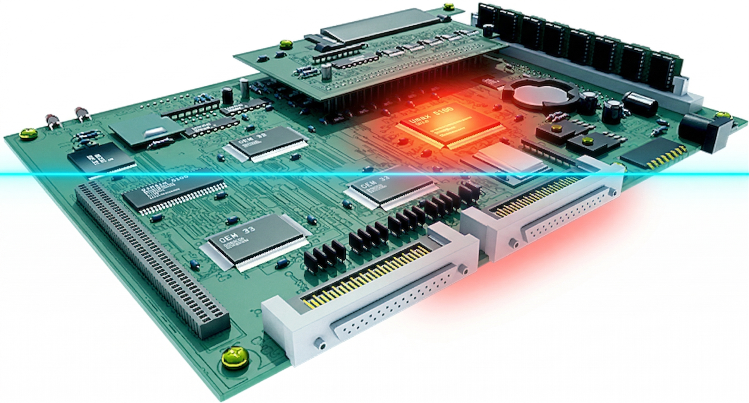
Figure 1. Illustration of electronic component image capturing during the pick-up stage of the ick and place machine. The component is being held up by the machine nozzle while its bottom side is being analyzed.
We obtain images from the production machines and utilize them in conjunction with advanced algorithms (Figure 1). As a typical production line processes on average around one million components a day, this provided the gateway to big data. Over the course of several years, we collected and analyzed approximately 5 billion components by deploying the system across tens of SMT (Surface Mount Technology) production lines [25], [26], [27]. The data was gathered and processed via a cloud platform capable of collecting from sites worldwide and centrally processing the data using cloud resources.
Our method for detecting counterfeits, defects, solderability issues, and corrosion was published in [25], [26], [29]. By applying this method to mass materials, we attained a unique position to evaluate the state of components from a statistical perspective. Consequently, we published work on the occurrence of corrosion and solderability issues in passive components [26]. Additionally, we documented several use cases of corrosion detected using this method, subsequently verified by lab analysis. Moreover, we devised a method to mitigate the risk of cracks in MLCCs (Multilayer Ceramic Capacitors) by early detection of evidence of corrosion in the soldering terminals, as we demonstrated that corrosion serves as a precursor for crack development [12].
The IPC-A-610H standard [3] serves as a comprehensive guide for assembled PCBs, outlining specific criteria for identifying defects and ensuring the quality of electronic assemblies. Other standards relate to the specific defect details as they appear in the IPC-A-610. In this work, we integrate the key compliance parameters outlined in IPC-A-610 with the presented AI-driven inspection method. We highlight the standard sections relevant to the presented method and demonstrate how the method can automatically detect these defects across all inspected components. The detection algorithm is only mentioned in this work and is elaborated in [12], [16], [30], [31], [32]. In this work, the novelty lies in adapting the methods to real-time operation.
Compliance with IPC-A-610H and IPC-J-STD-001 Standards
The IPC-A-610 standard [3] serves as a comprehensive guide for assembled PCBs, outlining specific criteria for identifying defects and ensuring the quality of electronic assemblies. Other standards relate to the specific defect details as they appear in IPC-A-610. This section integrates key compliance parameters from IPC-A-610 with the presented AI-driven inspection method, highlighting the standard sections relevant to the method and demonstrating automatic AI detection capabilities.
Defects on Component Leads/Terminations
Inspecting component leads is fundamental in ensuring alignment with IPC-A-610’s stringent criteria. Utilizing deep learning algorithms, our method examines each lead for damage or deformation, such as scratches, dents, distortions, peeling, and shorts, exceeding 10% of the lead’s diameter, width, or thickness.
The method utilizes deep neural networks trained by millions of examples on how a component of different package cases

Figure 2. Example images taken by the pick-and-place SMT machine during component pick-up. A: A Small Outline (SOT) component with leads and body deformation. B: A Ball Grid Array (BGA) component with damaged soldering balls. C: Passive components with termination defects.
visually appears. The algorithm breaks the images into a features map that is finely tuned to the normative visual features of each component and can identify any case of deviation from this norm. The deviation is first evaluated by unsupervised methods to capture the visual features that statistically deviate from the norm in each of the feature map objects. This methos illuminates the deviations and allows for a second stage of classification network to identify the defect. Figure 1presents examples of defects on the bottom side of electronic components detected during the mounting process in an SMT line.
Bent or Warped Leads
The presented method excels in detecting bending and indentation issues in component leads, in line with IPC-A-610 Section 8.3.5.8. Advanced evaluation techniques ensure any deviation beyond the specified threshold is flagged for further assessment. Figure 4 shows examples of bent and warped leads, with deviations exceeding 10% of the lead’s width.
Bent leads are relatively severe defects that affect the placement accuracy and reliability. Sideway bend is relatively easy to detect as the lead’s parallelism is broken by the deviation. The algorithm addresses bent and warped leads by capturing each individual lead as an object and analyzing its consistency first by itself and then in relation to its neighboring leads, and finally to the component body. The analysis is performed based on deep neural network sets trained to capture deviations from norm in the shape of the leads. A more complex case of leads deformation is met in the case of connectors and multiple leads connectors. Figure 2 presents example images of components with bent leads.
Connectors Inspection and Qualification
Inspecting connectors poses significant challenges due to their intricate lead structures and the high density of multiple leads, which can hinder the effectiveness of conventional machine vision systems. The IPC-A-610 standard provides detailed criteria for the inspection of connectors, specifically focusing on two primary types of pin installations: edge connector pins and press-fit connector pins. These

Figure 3. Example images taken by the pick-and-place SMT machine during component pick-up. A: SOT component with all bent leads. B: QFP component with bent leads. C: IC with Bent lead.
connectors, typically installed using automated equipment, necessitate meticulous visual inspection to ensure proper assembly and functionality.
For connectors assembled on the SMT line, real-time bottom-side imaging during mounting can be effective. However, connectors often feature top-side or right-angle connections that are not visible during the mounting process, requiring alternative imaging strategies. For top-side vertical connectors, Automated Optical Inspection (AOI) images are utilized, whereas right-angle connectors may necessitate a specialized vision system designed to capture images from different angles.
The quality of the images captured is crucial for the accurate inspection of connectors, as these components typically feature extended sections that must be completely visible to the algorithm for effective analysis. Therefore, a visual system with optics similar to those used in AOI systems is most suitable for capturing detailed and comprehensive images of connectors. This ensures that all parts of the connector are adequately inspected, allowing for precise defect detection and enhancing the overall reliability of the inspection process.
Edge Connector Pins (Section 4.3.1 in IPC-A-610)
Edge connector pins play a role in ensuring reliable electrical connections. The standard emphasizes the correct positioning of the contact shoulder relative to the land, which must allow sufficient clearance for an extraction tool.
One critical defect identified in the standard is a contact positioned above the insulator, classified as a defect across all classes (1, 2, and 3). The AI inspection system accurately analyzes the position of each contact, promptly flagging any misalignment to ensure compliance with the standard.
Press-Fit Pins (Section 4.3.2 in IPC-A-610)
Press-fit pins must maintain precise alignment, height, and overall integrity to ensure both proper electrical contact and mechanical stability. Given the mechanical stress these components endure during installation, thorough inspection is essential to detect any deformation or misalignment.

Figure 4. Example images of connectors. A: Bottom view during the mounting process with detected leads coplanarity. B: Bottom view of connector with bent leads. C: Side view of a right-angle connector with defective pin.


Figure 5. Press-fit components inspection after assembly. (TOP): Press-fit pin protruding from bottom side of PCB where the 2 left side pins are well protruding where the right-side pin is only partly protruding. (BOT): Left – Press-fit with soldering. Right – Press-fit with no soldering.
The standard specifies that pins bent off-center by more than 50% of the pin’s thickness are classified as defects. The AI system, with its deep learning models, is adept at recognizing even slight deviations in pin alignment, automatically flagging those that exceed the acceptable threshold. Another critical defect is twisted pins, which compromise the connector’s functionality. The AI system identifies such deformations, ensuring all pins remain properly oriented. Additionally, the height of each pin is measured by the AI inspection method, comparing it against specified tolerances to detect any pins that are out of specification.
Mechanical Integrity and Functionality of Connectors (Section 9.5 in IPC-A-610)
Beyond the specific criteria for edge and press-fit pins, IPC-A-610 Section 9.5 emphasizes the importance of maintaining the mechanical integrity and functionality of the connector housing.

Figure 6. Bottom view images of component with oxidation / contamination / corrosion on the soldering leads. Images taken from the bottom side during pick and place process. A: Bottom Termination Component’s (BTC) with contamination on the soldering terminations. B: Connectors with corrosion on the soldering leads. C: Passive components with corrosion and burn marks on the terminations.
Defects such as burrs, cracks, and deformations that affect the housing’s mechanical integrity or functionality are considered critical across all classes. The AI inspection system can detect these issues, automatically rejecting any connectors that fail to meet the mechanical standards. Another common defect is pins bent off-center by more than 25% of their thickness or diameter, which the AI system precisely measures to ensure compliance with the stringent IPC-A-610 requirements.
Corrosion and Cleanliness
The system is adept at detecting corrosion and residues on metallic surfaces, ensuring compliance with IPC-A-610 cleanliness and surface appearance standards. By identifying discoloration or corrosion promptly, it ensures components meet IPC-A-610 parameters. Figure 5 displays components with corrosion and contamination detected by the AI algorithm.
Cleanliness – Foreign Object Debris (FOD)
IPC-A-610 places a strong emphasis on cleanliness, specifically with regard to foreign object debris (FOD). The proposed method assesses components for contamination, identifying and flagging any debris or residues that exceed the limits established in IPC-A-610 Sections 10.6.2 and 10.6.3. A critical aspect of debris detection involves pinpointing the source of the debris rather than merely its size or the immediate risk it may pose, such as the potential to create shorts. Even small-sized debris can shift and accumulate, leading to significant damage. The primary goal is to determine whether the debris originates from contamination within the placement machine, disintegration of component terminations on the reel, or contamination during material storage or handling. FOD is also a concern within connectors and headers, as well as during post-assembly stages. Figure 7 displays examples of components where FOD was detected by the AI algorithm.

Figure 7. Examples of components with foreign object debris detected by the algorithm. A: BGA component with a foreign object debris detected. B: BTC with a foreign object debris nearing a short. C: FOD on a passive component large enough to cause a short. The size of the debris is not the important factor as the debris is free to shift. The main issue is detecting the source of the debris and eliminating the risk at the source.
Loss of Metallization, Delamination, and Peeling
Metallization loss is a significant defect identified by IPC-A-610 standards. The proposed method detects irregularities in metallization coverage, ensuring the functionality and reliability of components as stipulated in IPC-A-610 Sections 9.1 and 9.3. In some instances, disintegration of metallization is the primary cause of Foreign Object Debris (FOD). This loss of metallization suggests a weakened bond between the metallic layer and the component body, adversely affecting solderability and increasing failure rates during production. Although the soldering process might temporarily secure the bond during production and testing phases, the underlying weakness compromises the long-term reliability of the contact. Figure 8 displays examples of components with metallization delamination identified by the AI algorithm.

Figure 8. Examples of delamination identified by the algorithm: A: BGA component insulation delamination, B: Leaded component with terminations peeling, C: Passive components with termination peeling. Metallization loss reveals a fragile foundation between the termination and the component body, potentially impacting both the production failure rate and the long-term reliability of the bond.
Mounting Upside Down
Detecting components mounted upside down is an important quality control measure, as outlined in IPC-A-610 Section 8.3.2.9.2. The proposed algorithm flags any non-compliant mounting configurations, ensuring adherence to IPC-A-610 standards. While flipped components may be acceptable in certain contexts, they often require substantial rework when not permissible, as existing test methods may fail to detect such issues because the functionality appears unchanged. This oversight can lead to significant production inefficiencies and increased costs.
Detection of Coplanarity Issues Using AI-Driven Inspection Method
Coplanarity in electronic components, especially in connector pins and leaded components, is a critical parameter that ensures reliable solder connections. Coplanarity refers to the condition where all component leads or pins lie in the same plane, which is essential for the uniformity of soldering during assembly. The IPC-A-610 standard specifies stringent requirements for coplanarity across various types of leads, including:
- 3.5.8 Flat Gull Wing Leads – Coplanarity
- 3.6.9 Round or Flattened (Coined) Gull Wing Leads – Coplanarity
- 3.7.8 J Leads – Coplanarity
These sections dictate that all component leads must be aligned to prevent any disruption in forming an acceptable solder connection, which is vital for the functional integrity of electronic assemblies.
Detecting coplanarity issues using traditional methods can be challenging, particularly because the bottom-side view typically used during the automated mounting process does not ideally suit the detection of misaligned leads. However, the AI-driven inspection method proposed in this work leverages advanced imaging and deep neural network algorithms to overcome these challenges.
The AI system employs a technique where it analyzes the geometric shapes of the leads as captured from the bottom-side perspective. In a perfectly coplanar arrangement, leads appear as rectangular shapes when viewed perpendicular to the camera. However, any deviation from this coplanarity causes the leads to tilt upward or downward, altering their shape into a trapezoid and affecting their apparent length in the captured image. This deviation in geometry is critical as it indicates a potential coplanarity issue. Figure 9 presents examples of components detected with coplanarity issues.
The deep neural network algorithm is specifically trained to recognize the standard rectangular shape of normal, coplanar leads. When a lead displays an altered trapezoidal shape or shows a variation in length, the algorithm detects these as anomalies, flagging them for further inspection. This method allows the AI to analyze all leads and pins on components

Figure 9. Leaded Components Exhibiting Coplanarity Issues. A: SOT component displaying slight coplanarity deviations. B: SOT component with a foreign object affecting pick-up orientation, showcasing visible lead angle alterations. C: QFP package case with an array of warped leads, demonstrating significant coplanarity challenges.
and connectors efficiently, without necessitating rigorous individual measurements.
This AI approach not only enhances the detection of coplanarity issues but also significantly streamlines the inspection process. By automating the analysis and leveraging real-time data processing, the method improves the accuracy and speed of quality control in PCB assembly. Moreover, it ensures compliance with the IPC-A-610 standards, supporting the assembly of high-reliability electronic products.
This paper has outlined a transformative approach to electronic component assembly by integrating AI-powered deep learning techniques for real-time, inline inspection. By leveraging existing pick-and-place machine infrastructure, this method captures high-resolution images of components during assembly, which are analyzed instantaneously to detect and address various defects such as damage, corrosion, and structural irregularities.
The adoption of this AI-driven inspection strategy marks a significant shift from traditional reactive quality assurance practices to a proactive model that not only anticipates but actively prevents the occurrence of defects. This proactive detection is crucial for maintaining the stringent standards set by IPC-A-610 and IPC-J-STD-001, ensuring that each component meets the highest quality criteria before integration into final products.
Through detailed examples and practical applications, the research presented here demonstrates the efficacy of deep learning algorithms in identifying and rectifying defects, significantly enhancing the reliability and quality of electronic manufacturing processes. The integration of this technology into electronic manufacturing service (EMS) workflows not only boosts production efficiency but also reduces potential disruptions, leading to substantial cost savings and smoother production flows.
Ultimately, this innovative inspection method not only satisfies current manufacturing standards but sets a new benchmark for quality assurance in electronics manufacturing, offering a clear pathway for manufacturers to elevate their production capabilities and achieve unprecedented levels of component reliability and efficiency. The continued development and integration of AI technologies in this field are poised to redefine the landscape of electronic component assembly, ensuring that manufacturers remain at the forefront of technological advancements and quality control.